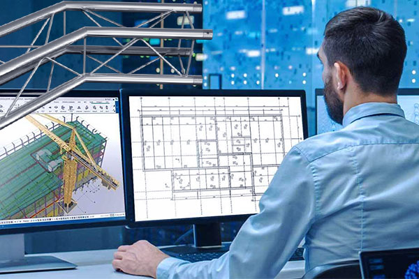
In the construction industry, steel detailing has a crucial role in the construction and manufacturing of steel components used for various projects. A detailed plan, drawings, 3D model, and documents prepared in the steel detailing process supports precise and accurate fabrication and erection of steel components at the site.
Tekla Structure, steel detailing software, guides the steel detailing process from concept to fabrication. Tekla gets widely acknowledged for its flexibility, quality output, and efficient working ability. The use of software results in steel fabrication drawing, a 3D modeling environment that enhances steel structures quality, automation BOM generation, automatic sync for management of drawings and views, etc. Tekla Structures is available in different configurations and environments.
Tips to Use Tekla for Your Steel Detailing Project
Here is the list of top ten tips that will guide you in using Tekla Structures for steel detailing.
1. Create Any Type of Steel Structure in the Software
Tekla structures allow to creation information-rich 3D model comprising all structural data required to build and maintain any structure type.
For efficient working, you need to be aware of basic working methods in Tekla structures, such as working with grids and views, zooming and rotating the model, creating, selecting, and moving the model, and defining the work area and coordinates that affect the work, etc.
Next, create a model of structural elements. For example, to create columns go to the Steel tab and click on Columns. Tekla structures create the Steel columns using the steel column properties in the property pane and at the level defined in the properties. For changing the column properties, you can also double-click the column to open properties and modify them.
After creating all the objects, you can use tools like the Fly command, Inquire command, and measure command for traveling through the model. And get specific information about any object, get distance measurements, detect clashes, and others.
2. Generate the Shop and Erection Drawings
You can generate the fabrication or shop drawing in Tekla structures using creation review for a controlled creation process or smartly create if you want to create drawings immediately.
For erection drawings, follow these steps.
- Download and Install the Erection drawing package from the Tekla warehouse and open a Tekla model with GA drawings.
- Then, click the Application and Components button in the side pane to open the catalog.
- Search and open the Erection drawing and double-click to open the dialogue window.
- Make the required modification and select the main part, column, beam, contour plate, etc.
- Click on create and select the grid for creating drawings.
3. User-friendly for Steel Detailers and Fabricators

Tekla offers an automated shop drawings process, automated clash detection, integrated BIM and fabrication MIS, and many other features. Tekla generates drawings in five parts, i.e., single part drawing, assembly drawing, general arrangement drawing, multi drawing, and cast unit drawing.
With an automatic clash detection feature, the software identifies any clash in the model before it progresses to the site or floor. BIM and fabrication MIS integration provide real-time fabrication management, CNC processing data, material handling, and robotic assembly. Multiple users can work on a single project at the same time, irrespective of location, time zone, or internet speed.
4. Create the Output Files of NC, Dxf, Fabtrol, and KSS Files
Tekla structures produce NC files in DSTV format in the current model format. We can also generate NC files in DXF format by converting DSTV files to DXF files. Select the information to get included in the NC files and NC file headers and define needed pop-mark and contour mark settings.
FabTrol is an MRP system used to manage estimation, inventory, and production by fabricators. Data can be written to FabTrol using a KISS format export or directly through text-based reports from Tekla Structures. The tracking information entered in Fabtrol can get reimported back to Tekla Structures via FabTrol XML import.
5. Coordinate with Other Structures by Inserting the Coordination IFC Model
Tekla Structures allows to insertion of IFC models as reference models and optionally converts the inserted IFC objects into native Tekla structures objects. It helps create a structural model and coordination to avoid rework in the early modeling phase. We can use direct conversion or selected IFC reference objects using conversion change management.
The inserted IFC reference model supports all the sub-objects of the IFC building element class and sub-objects of the IFC product, including architectural entities, structural entities, and building services entities.
6. Create the IFC Model, DWG, and PDF Files from the Software

We can export Tekla Structure models as IFC models. All the basic parts in the Tekla Structure model can be exported, such as beams, columns, braces, slabs, etc. IFC support functionality supports IFC2X3 and IFC4 schemas. You can also export the Tekla structure drawing to a 2D DWG file.
In the DWG drawing export, we can easily set layers for different objects, use filters to separate objects, use base points, model coordinates, embed images, etc.
Tekla also creates PDF files using any standard pdf printer such as adobe acrobat, pdfFactory, etc.
7. Share the Tekla Model
To share a model in Tekla model sharing, you need to log in with Trimble identity in Tekla Structures.
- First, open the single-user model that you want to share.
- On the File menu, click on sharing > start sharing.
- Select the service from the service list in the Start sharing dialog box.
- If needed, Select the code and description of the model.
- You can invite other users to share your model by typing their email addresses in the Invite Users box and selecting their role.
- Click on Add button to add users to the model.
- Finally, click on the Start button to start sharing your model.
8. Clash Check in the Model

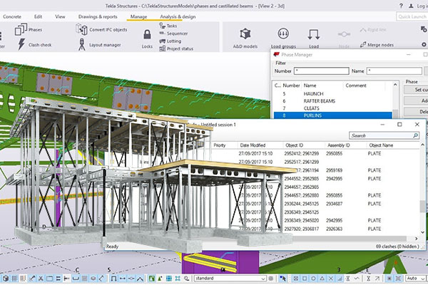
Tekla’s Clash Check allows you to find clashes between reference model objects, reference models, and native Tekla Structures.
- Set the minimum distance between reference model objects, native Tekla structures parts, and reference model objects using the Clash Check dialogue box.
- Select the objects to include in the clash check from the model and click on the progress button.
- Select a row in the list of clashes, double click to zoom, and for the center view of selected objects.
- Remove or modify the object and re-run it to re-check clashes.
9. Create Advance BOM Report Post Member Placement
We can create an advance bill of materials (BOM) by using the Combine module in Tekla EPM. We can add combining jobs manually or import them as Microsoft Excel Worksheets, KISS, or IFC files. The information in the imported files gets automatically transferred into relevant fields of the combining module.
We can combine and re-combine materials using the different lengths of materials after they enter the combining module. The Combined materials can then get sent to a requisition for pricing or purchase order. Tekla EPM marks materials sent for purchasing for sending them again for purchasing if required.
10. Rotate Model and Identify Erection Feasibility, Welding Possibility, Bolt Insertion, and Tightening Issues
In Tekla, we can rotate objects in a model by rotating around any line of our choice. For rotating objects around the Z axis, use the Z option in the Rotate dialog box. To change the settings for rotating objects in Tekla, use Copy-Rotate and Move-Rotate dialog boxes.
Using the model, we can identify direction feasibility, the possibility for welding for different components, bolt insertion, and tightening issues in Tekla.
eLogicTech Solutions Expertise in Tekla for Steel Detailing
eLogicTech has a team of steel detailing with expertise in various versions of Tekla Software. The team works in several environments of Tekla Software and has years of vast exposure in steel detailing of industrial, commercial, and residential projects. eLogicTech Tekla experts help you achieve precise and accurate steel detailing, drawings, and required documents.


