

Revit’s adaptive components are a powerful tool for 3D and architectural modeling, allowing us to have infinite family forms with different parametric values. The application of adaptive components in Revit is endless because of its smart nature.
The adaptive component feature in Revit was added around ten years ago to solve the former limitations of Revit, such as moving beyond square shapes. Adaptive components originated from a massing environment and still play a crucial role in the workflow of adaptive components.
Adaptive Components and Their Difference from Regular Components
Adaptive components in Revit are an adaptation of the pattern-based curtain panel and can flexibly adapt to many unique contextual conditions. We use adaptive components when there is a need to adopt a family at different positions using parametric rules. For instance, we can use adaptive components in repeating systems generated while arraying multiple components, conforming to user-defined constraints.
In Revit, users can create dynamic adaptive components with the help of adaptive components. Adaptive components differ from regular components, i.e., families. In regular components, the geometry of the family relates to one unique insertion point or a maximum of two for line-based families. However, in adaptive components, the family geometry relates to more than one insertion point. They can grow differently based on the position of insertion points and create dynamic adaptive components.
Creation of Adaptive Components in Revit
Adaptive point is the key component as snapping to these flexible points results in adaptive components. Adaptive points are the modified reference points used for designing an adaptive component in the conceptual design environment. These points help in component placement or as shape handles usage. When used for placement, these adaptive points get numbered in the placement order while components get loaded.
The two types of family templates for creating adaptive components are
Metric Generic Model Adaptive
We create adaptive points by modifying reference points in a generic adaptive family based on the Generic Model Adaptive. rft family template. When a reference point is made adaptive, it becomes a placement point by default. And geometry drawn using these adaptive points results in an adaptive component.
Metric Generic Model Pattern Based
We can create pattern component families from the generic model pattern-based Revit family template and then apply pattern components to the surface of the conceptual mass.
Procedure to Create Adaptive Components
The steps to create an adaptive component in Revit are as follows.
1. Select Family Template
First, we should choose a family template to create the adaptive component. For generic models, we can choose ‘Metric Generic Model Adaptive. rft’ and for patterned panels- select ‘Metric Generic Model Pattern Based.’
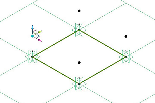
2. Create Adaptive Points
In the case of a Metric Generic Model Pattern-based template, adaptive points are already created in a square shape, whereas, in Metric Generic Model Adaptive, a user must create adaptive points.
For creating adaptive points, insert some reference points and make them adaptive in a generic adaptive family. When a reference point is made adaptive, it gets a placement point by default. The numbering of these adaptive points is based on their placement order. We can change the number by selecting it, and others will adjust accordingly.
3. Create Geometry
We need to define X, Y, and Z work planes for each adaptive point before modeling any piece of geometry. For surface creation, ensure 3D snapping gets turned on and draw a reference line from point to point. The steps required to do this are
- Pick the Create/Modify Tab > Model Lines / Reference Lines.
- Turn on the 3D Snapping from the options bar.
We can select a model or reference line based on our purpose and suitability.
Model lines are actual lines or edges that appear in the model when the family gets loaded into the project.
We can draw model lines in order of the reference point numbers and ensure lines are linked to the adaptive points. However, a few times, it gets difficult to link the lines to the points appropriately.
So, we can select two points through the ‘Spline through points’ tool, and lines get automatically attached to the point. We get a straight line if we choose only two points and a spline curve through the points when we select three or more points.
Reference lines are reference elements with no visual entity while loading the family into the model. They have four associated work-planes-two intersect in the longitudinal dimension to define the line, and rest two are perpendicular to the line at its ends.
Reference lines follow the adaptive points wherever they move. In the case of a closed curve, we can convert the lines into a surface or solid shape by clicking on “Create Form.”
Adaptive points and the input data help us create different types of geometry. For example, if we place a reference point in any reference lines and draw a circle in the perpendicular plane to the line, we get a sweep while applying “Create Form” to the circle and the reference lines.
4. Reporting Parameters
A reporting parameter is a parameter type that drives its value through a particular dimension in the family model. The reporting parameter extracts the value from a geometric condition used for reporting the data to a formula or as a scheduled parameter.
We need to set a reference plane containing the dimension line for creating a parameter in an adaptive component. If a parameter gives information related to the adaptive geometry, it is a reporting parameter.
The reposting parameter gives different values for different adaptive components and can read the dimension of a geometry.
5. Apply Adaptive Components to the Project
After creating the adaptive component and scheduled parameter, we can load the family in the project.
The two different ways of placing adaptive components are
- Selecting a reference plane
- Reference Geometry
We should select as many points as the family’s adaptive points for placing an adaptive component.
6. Nest an Adaptive Component in Family
We should nest an adaptive component in the family for repeating an adaptive component several times.
7. Nest Family into Adaptive Component
Generally, we use profile forms to create 3D forms.
It is valuable to nest the profile as a family containing all the parameters for an adaptive component following the extrusion of a 2D profile.
We can nest 3D families as part of our adaptive component by placing them on a work plane of adaptive points. The inserted family changes position according to the placement of the adaptive points.
Usage and Advantage of Adaptive Components

The use of adaptive components varies from pattern panel families, adaptive component families, conceptual massing environments, and other projects.
Some of the advantages of adaptive components are
- We can use adaptive components for railings and mechanical and electrical fixtures.
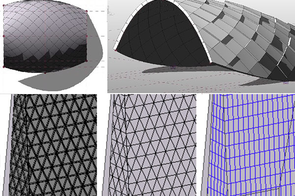
- Adaptive components are very effective in curtain walls.
- We can use them in façade penalization.
- We can have many forms of adaptive component families without creating different parametric values for each.
Adaptive Components: A Powerful Tool for 3D Modeling
Adaptive components help us create families, flexible enough to adapt to several unique contextual conditions.
Even though adaptive components do not have 2D capabilities, they are a powerful tool for 3D modeling. eLogicTech Edge, an engineering firm and a BIM service provider, uses adaptive components for 3D modeling of railings, mechanical and electrical fixtures, and other architectural modeling effectively.


