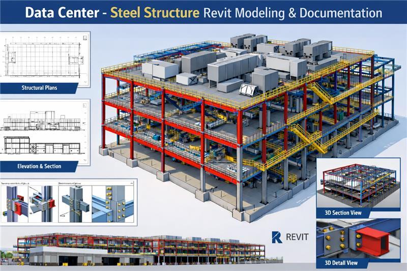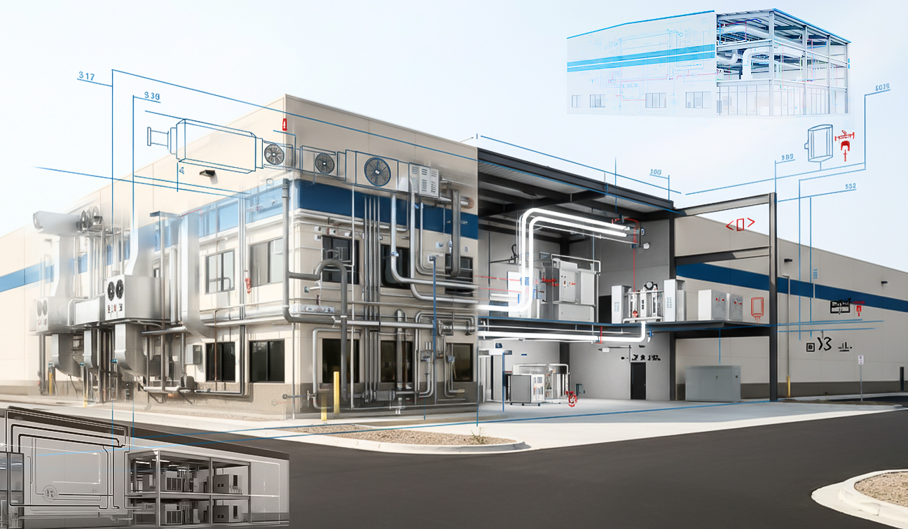
The client holds expertise in all aspects of steel fabrication and erection projects and delivers the best steel solution for a variety of requirements. An extensive experience of over 20 years gives the client in-depth knowledge to tackle steel erection projects, from portal frame construction to complex structures.
With a large steel workshop, the client can handle large structural steel fabrication and erection jobs, a size ranging from 10 to 500 tonnes. And for on-site erection, it gives flexibility by deploying its labor force, cranes, and access equipment.
Input Information and Client Requirements
The vast exposure of eLogicTech in structural shop drawing and steel detailing using Tekla software compelled the client to approach us. They were working on a single-story commercial project and came up with a requirement to develop a detailed 3D model and shop drawing for beams, columns, braces, rafters, and purlins. The mandated software for the project was Tekla Structure-2021.
As input information, the client provided us with structural and architectural drawings of the commercial project in PDF format. We were assigned a tight deadline of four weeks to deliver the shop drawings and required documents.
Challenges in Measuring Dimension and Modeling Different Steel Parts
The drawings provided by the client had steelwork schedules, purlin, and grit schedules. The challenge was to align the exact dimensions of beams, columns, purlin, and grit, considering their different angels in the 3D model. Giving the 3D view of these components without any variation was crucial to generating an error-free shop drawing.
The eLogicTech team maintained thorough communication with the client to resolve queries during modeling and reduce any dimension variation of the steel components. The team also sought proactive help regarding the missing information on the steel component dimensions and related connections.
The course of Action Followed by the eLogicTech Engineering Team
Understanding the complexity of the structure, the eLogicTech team followed a set of actions to deliver quality results within the set timeline. The process that our team followed are
Kick-Off Meeting We formed a Tekla experts’ team of eight members after getting the project from the client. The team conducted an initial level meeting to discuss the project, the complexity of the structure, and schedules.
Raised RFI’s After the kick-off meeting, we reviewed the drawing PDFs provided by the client and raised RFIs to get the missing dimension and connections details.
Model Check The team developed the 3D model, and we further checked at each stage, such as Grid place, member placement, and connections, to minimize error and ensure quality.
Updated Connection and Drawings After receiving the RFI response, the team updated the connections and drawings in the 3D model. The shop drawings were generated based on the updated model and released for first-level checking.
Quality Check Now, we sent the drawings for a final QC check. Then, the team updated the QC comments, and finally, an error-free drawing, along with the related documents, got released and sent to the client.
Takeaways: A Strict Adherence to Quality and Timeline
eLogicTech Tekla experts gave a 3D perspective of the required steel structure and components, added with a detailed Shop drawing. A better understanding of the client’s requirements and the building standard helped us deliver quality results within the set timeline. The team strictly followed their set deadline for each task, and a regular check at each stage helped us optimize the quality of the drawing. Handling such a complex project made the eLogicTeam more versatile and skilled. If you have any structural detailing requirements, approach eLogicTech experts to avail precise and in-time delivery.
Need Help?
Don't hesitate to contact us for more information about company or service


.jpg)
.jpg)


