


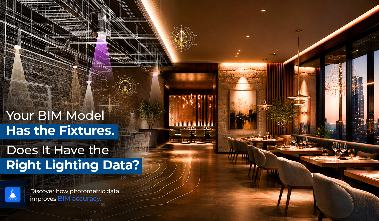
There’s a moment on almost every hospitality project where the lighting design gets found out. Sometimes it happens at permit review, when the plan checker asks for point – by – point calculations the team never actually ran. Sometimes it happens after installation, when the restaurant owner walks the dining room at 8 PM and asks why the tables feel like an office and the bar feels like a cave. Either way, the problem started months earlier — in the model.
Most Revit models contain lighting fixtures. Very few contain lighting data. That distinction is the difference between a rendering that looks convincing and a calculation that holds up in the field, and it’s worth understanding in detail if you’re an architect, MEP engineer, or lighting designer working on hotels, restaurants, or any space where light is the experience.
A fixture family without photometric data is a picture, not an instrument
Every legitimate photometric calculation starts with an IES file — a standardized text file, defined by ANSI/IES LM-63, that contains the measured luminous intensity of a specific luminaire at every angle, taken from laboratory testing under the LM – 79 method. It describes exactly how much light leaves the fixture, in which directions, and at what intensity. Candela values, lamp data, luminous opening dimensions — the complete optical fingerprint of that one product.
Here’s the part that gets glossed over on real projects: an IES file corresponds to a single fixture model. Not a product line. Not “a 6 – inch downlight, roughly.” One SKU, one photometric web. Swap the specified fixture for a “visually equivalent” alternate during procurement without swapping the IES file, and every calculation downstream is describing a luminaire that no longer exists on the project.
Without the fixture – specific IES file loaded into the family, a photometric plan is an estimate dressed up as a calculation. It might be a good estimate. On a hospitality project with layered lighting, dimming scenes, and a design intent measured in mood rather than lumens, it usually isn’t.
Where BIM lighting accuracy actually breaks down
The teams that get burned on lighting are rarely careless. The failure points are subtle, and most of them live inside settings nobody reviews.
The IES file doesn't match the specified fixture.
Generic Revit families ship with placeholder photometric webs. If nobody replaces them with manufacturer data for the actual specified product — pulled per SKU from the manufacturer’s site — the model calculates light from a fixture that was never on the drawings. This is the single most common gap we see when auditing lighting content in client models.
Surface reflectances come from shading colors, not reality.
This one surprises even experienced Revit users. Calculation engines that read the Revit model derive surface reflectance from the material’s Graphics/Shading color — not the Appearance asset used for rendering. A wall shaded dark gray for graphic clarity gets treated as a dark, light-absorbing surface in the calculation, even if the real finish is off-white paint. In a hotel corridor where reflected light carries most of the ambient level, a wrong reflectance value can shift results by 20 to 30 percent before a single fixture moves. Industry practice defaults to 80/50/20 for ceiling/wall/floor — but somebody has to actually verify and map those values.
Spaces and rooms aren't set up for analysis.
Point-by-point calculation needs bounded volumes. If Revit Spaces don’t extend to engage ceiling – mounted fixtures, or a restaurant’s open dining/bar/lounge zones aren’t separated for calculation purposes, results get averaged across areas that were designed to feel completely different. A dining room average of 15 footcandles tells you nothing when the design intent was 30 fc on tabletops and 5 fc at the perimeter banquettes.
The calculation happens outside the model — and drifts.
The traditional workflow exports geometry to a standalone tool like AGi32 or DIALux, runs calculations there, then manually reconciles results with the Revit documentation. Every export is a snapshot. The architect moves a wall, the interior designer changes a ceiling finish, and the lighting calculation quietly becomes fiction. Tools like ElumTools solved this by putting a full radiosity calculation engine directly inside Revit, running point-by-point illuminance on the live model geometry, materials, and fixture families — no export, no drift, results visible in Revit views and schedulable like any other data.
Why hospitality projects punish sloppy photometrics harder than anything else
An office lighting layout that misses design levels by 15 percent is a code conversation. A restaurant lighting layout that misses by 15 percent is a business problem for the owner.
Hospitality lighting is layered by necessity — ambient, task, and accent working together, usually anchored around 2700K warmth, high CRI (90+) so food and skin tones read correctly, and dimming scenes that carry a space from breakfast service to late-night bar. The visual tasks are demanding and specific: tabletop illumination in dining rooms, glare control at bars, wayfinding levels in corridors that feel intimate rather than institutional. And energy code compliance — ASHRAE 90.1, IECC, Title 24 in California — has become one of the defining constraints of hospitality lighting design, because decorative fixtures burn through lighting power allowances fast.
Brand-flag hotel projects add another layer: multiple stakeholders reviewing and approving the design, most of whom don’t read footcandle tables. Getting a scheme approved means pairing photometric values with clear visual representations — pseudocolor illuminance maps, renderings driven by real IES data, calculation summaries the ownership group can actually interpret. That documentation quality is often what separates a smooth approval cycle from three rounds of resubmittal.
Exterior work brings its own trap. Many local ordinances now regulate light trespass down to fractions of a footcandle at the property line, which means site photometrics for hotel entries, patios, and parking need to be modeled honestly before construction — not defended after a neighbor complains.
What a disciplined photometric-in-BIM workflow looks like
On the projects we support, the workflow that consistently produces defensible results looks like this. Fixture families get verified first — every specified luminaire carries its manufacturer IES file, checked against the actual catalog number on the fixture schedule, with wattage and lumen data aligned. Material reflectances get mapped deliberately, using category overrides or verified per-material values rather than whatever the shading colors happen to imply. Spaces get modeled and bounded to match how the calculation needs to read the building, including separators in open-plan hospitality areas.
Then the calculations run where the model lives. In-Revit engines handle point-by-point illuminance per space, with emergency egress lighting calculated as a separate direct-only mode against the emergency – designated fixtures — a compliance deliverable in its own right. For repetitive work — a 200 – key hotel with a dozen room types, or a restaurant group rolling a prototype across 30 sites — Dynamo scripts automate fixture placement from the layout logic, batch the calculation setup, and push results into schedules, which turns a week of manual photometric drudgery into an afternoon.
The output isn’t just a compliant plan. It’s a model where the lighting documentation, the calculations, the fixture schedule, and the visualizations all describe the same building — and stay synchronized when the design changes, because on a hospitality project, the design always changes.
The cost of skipping this is paid in the field
Every gap between modeled light and installed light eventually surfaces as something expensive: an RFI when the contractor can’t reconcile the fixture schedule with the photometric plan, a rejected energy compliance submittal, a value – engineered fixture swap nobody re-calculated, or the worst version — a finished space that fails the owner’s walkthrough and triggers change orders on installed work. Photometric rigor in the model is cheap. Photometric corrections in the ceiling are not.
At eLogicTech, photometric calculation support is part of how we deliver MEP and lighting design services for hospitality and commercial projects — IES-verified fixture content, calculation – ready Revit models, point-by-point analysis in Visual, ElumTools, and Design Master, Dynamo automation for multi – site rollouts, and compliance documentation that clears review the first time. Twenty – five years of production BIM work has taught us exactly where these workflows break, and how to build them so they don’t.
If lighting accuracy has been a recurring pain point on your projects — or you have a hospitality job coming up where the lighting can’t afford to be a guess — talk to our team at elogictech.com/contact-us.


